


-
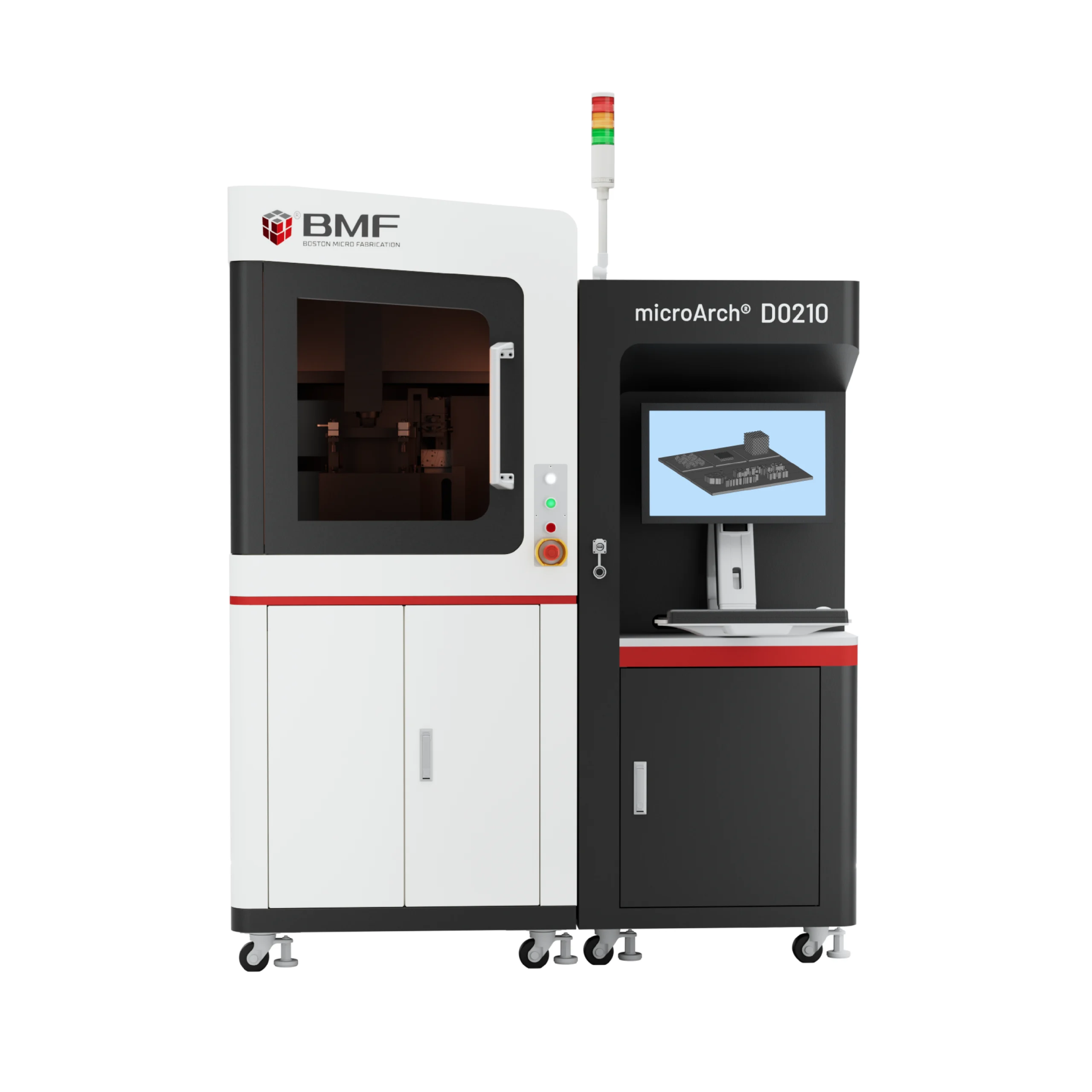
microArch ® D0210-2微米3D列印機
microArch® 微米精密3D列印 -

microArch® P150-25微米3D列印機
microArch® 微米精密3D列印 -
microArch® S130-2微米3D列印機
microArch® 微米精密3D列印 -

microArch® S140/P140-10微米3D列印機
microArch® 微米精密3D列印 -
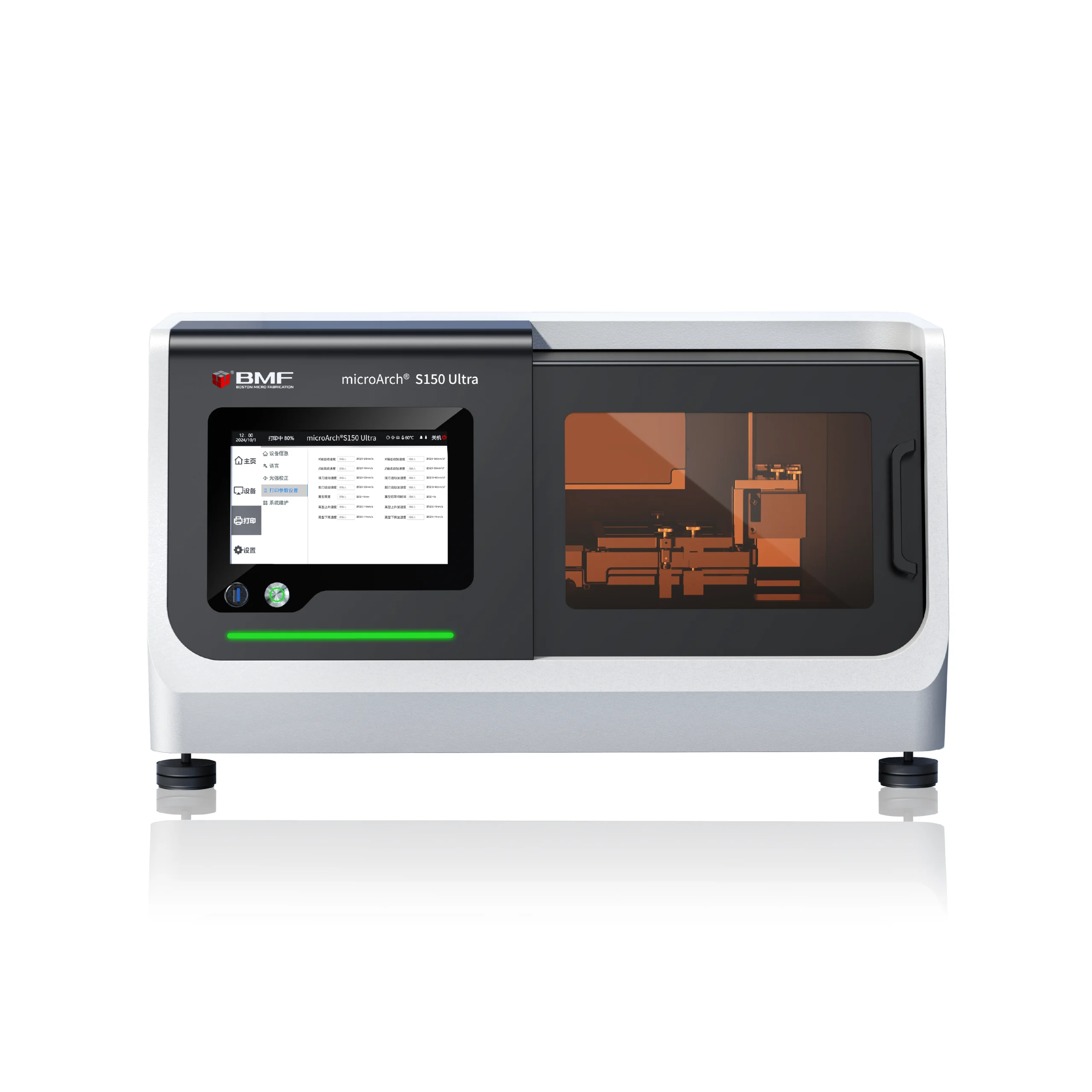
microArch® S150 Ultra-25微米3D列印機
microArch® 微米精密3D列印 -
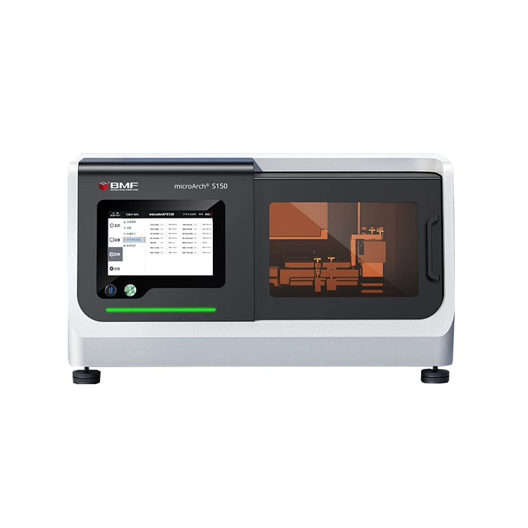
microArch® S150-25微米3D列印機
microArch® 微米精密3D列印 -
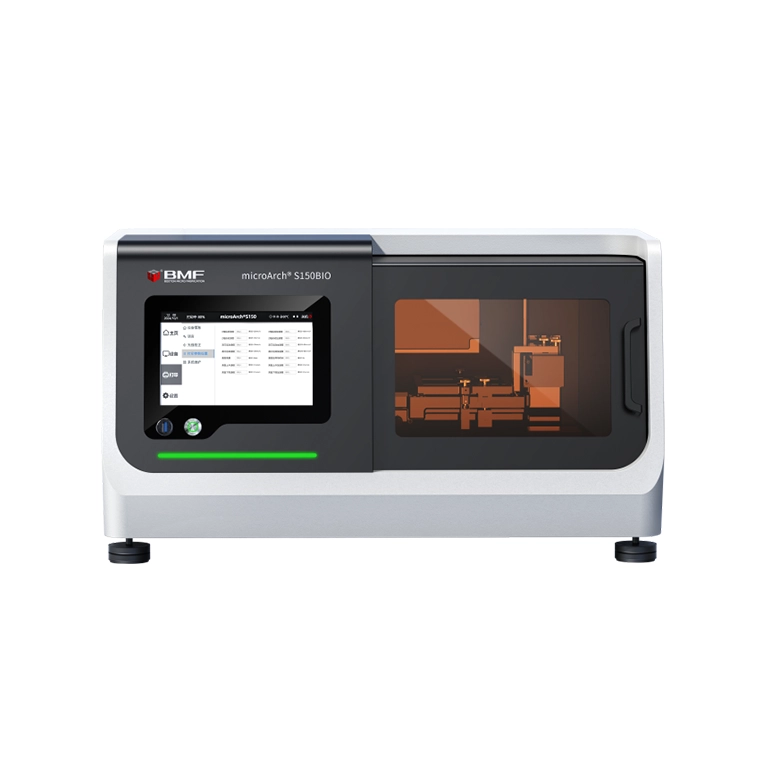
microArch® S150BIO-25微米3D列印機
microArch® 微米精密3D列印 -
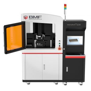
microArch® S230-2微米3D列印機
microArch® 微米精密3D列印 -
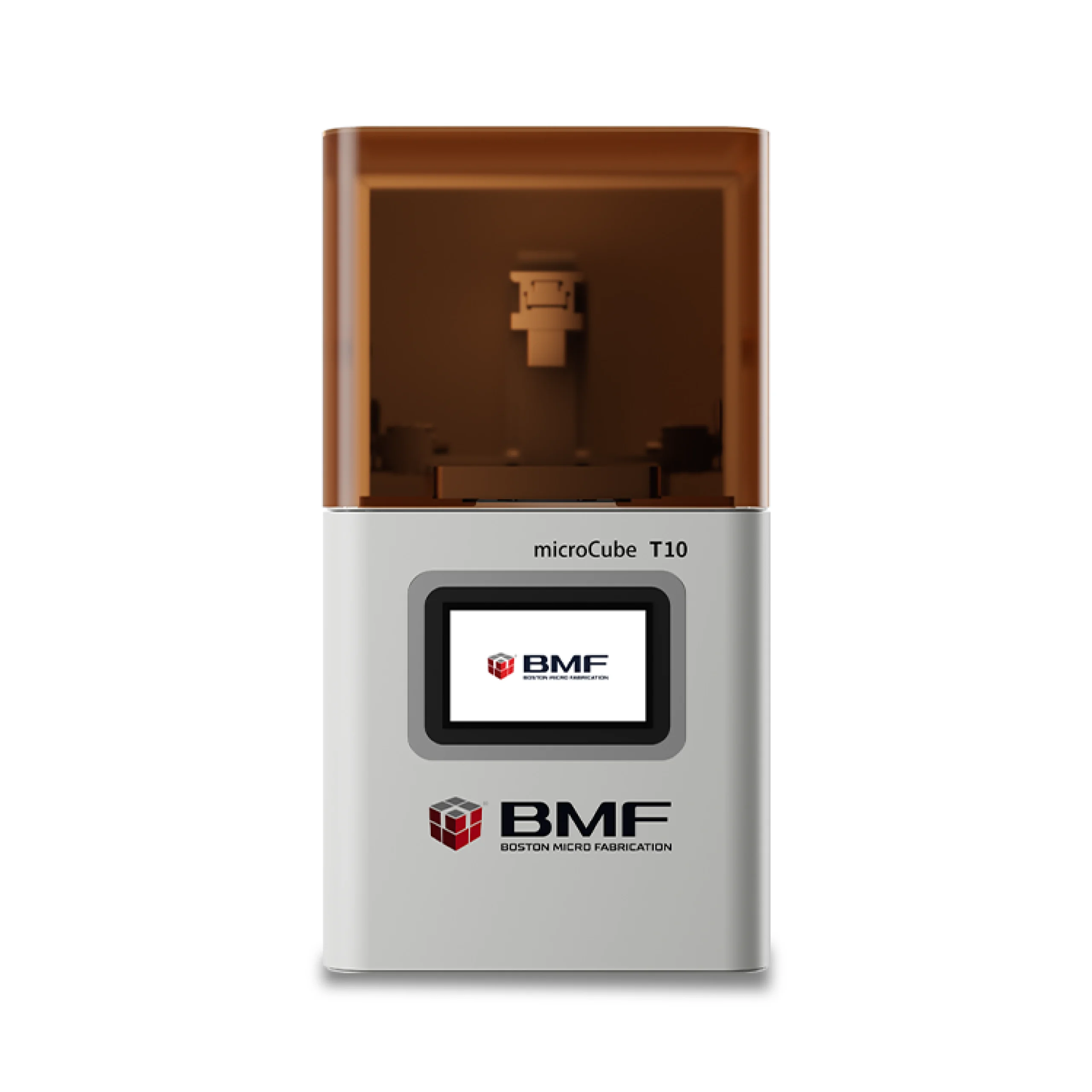
microCube T10-微米3D列印機
microArch® 微米精密3D列印 -
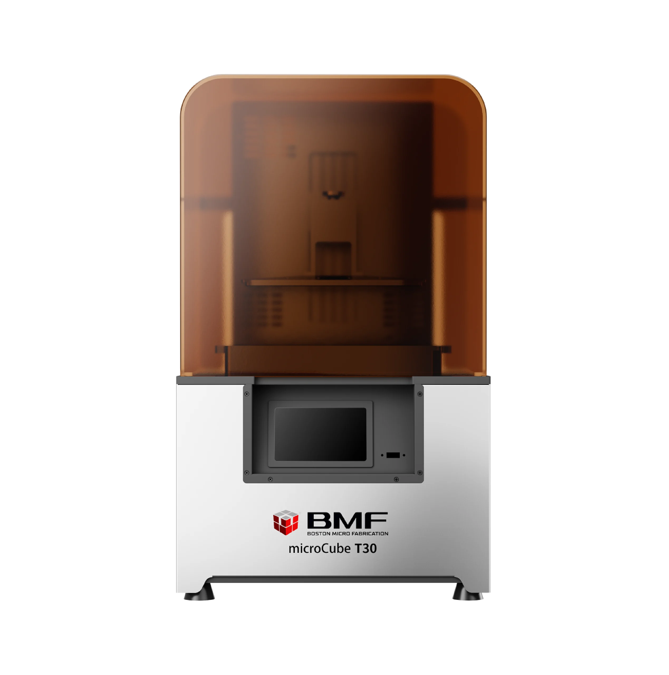
microCube T30-微米3D列印機
microArch® 微米精密3D列印